|
|
|
|
|
|
|
Mã sản phẩm:
6DR5...
Tên sản phẩm:
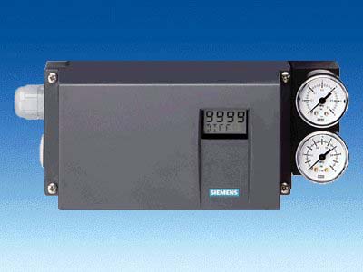
Positioners
|
|
The SIPART PS2 electropneumatic positioner is used to control the final control element of pneumatic linear or part-turn actuators
|
|
SIPART PS2 (all versions) |
|
|
General data |
|
|
Travel range (linear actuators) |
3 ... 130 mm (0.12 ... 5.12 inch) (angle of feedback shaft 16 ... 90°) |
|
Angle of rotation (part-turn actuators) |
30 ... 100° |
|
Assembly |
|
|
|
Using mounting kit 6DR4004-8V and where necessary with an additional lever arm 6DR4004-8L on actuators according to IEC 534-6 (NAMUR) with ribs, bars or flat face |
|
|
Using mounting kit 6DR4004-8D
on actuators with mounting plane according to VDI/VDE 3845 and DIN 3337:
The required mounting console has to be provided on the actuator side; shaft with groove and female thread M6 |
|
Controller unit |
|
|
|
Self-adjusting |
|
|
|
|
|
Self-adjusting or can be set as fixed value |
|
|
Self-adjusting or can be set as fixed value |
|
A/D converter |
|
|
|
10 ms |
|
|
≤ 0.05 % |
|
|
≤ 0.2 % |
|
|
≤ 0.1 %/10 K (≤ 0.1 %/18 °F) |
|
Cycle time |
|
|
|
20 ms |
|
|
60 ms |
|
|
60 ms (min. loop time) |
|
Binary input BE1 (terminals 9/10; electrically connected to the basic device) |
Suitable only for floating contact; max. contact load < 5 mA with 3 V |
|
Degree of protection |
IP66 to EN 60 529/NEMA 4X |
|
CE marking |
Conformity as regards EMC Directive 89/336 EC in accordance with the following standards |
|
EMC requirements |
EN 61326/A1 Appendix A.1 and NAMUR NE21 August 98 |
|
Material |
|
|
|
|
|
|
Glass-fiber-reinforced Macrolon |
|
|
GD AISi12 |
- 6DR5..2-... (stainless steel)
|
Austenitic stainless steel mat. No. 1.4581 |
- 6DR5..5-... (metal, flameproof)
|
GK AISi12 |
|
|
Aluminium AIMgSi, anodized |
|
Vibration resistance |
|
- Harmonic oscillations
(sine-wave) according to EN 60062-2-6/05.96 |
3.5 mm (0.14 inch), 2 ... 27 Hz 3 cycles/axis |
|
98.1 m/s² (321.84 ft/s²), 27 ... 300 Hz, 3 cycles/axis |
- Bumping (half-sine)
to EN 60068-2-29/03.95 |
150 m/s² (492 ft/s²), 6 ms, 1000 shocks/axis |
- Noise (digitally controlled)
to EN 60068-2-64/08.95 |
10 ... 200 Hz; 1 (m/s²)²/Hz (3.28 (ft/s²)²/Hz) |
|
200 ... 500 Hz; 0.3 (m/s²)²/Hz (0.98 (ft/s²)²/Hz) |
|
4 hours/axis |
- Recommended continuous duty range of the complete fitting
|
≤ 30 m/s² (≤ 98.4 ft/s²) without resonance sharpness |
|
Weight, basic device |
|
|
|
Approx. 0.9 kg (1.98 lb) |
- Metal enclosure, aluminium
|
Approx. 1.3 kg (2.87 lb) |
- Metal enclosure, stainless steel
|
Approx. 3.9 kg (8.6 lb) |
- Metal enclosure EEx d version
|
Approx. 5.2 kg (11.46 lb) |
|
Dimensions |
See Dimensional drawings |
|
Climatic class |
According to DIN EN 60721-3-4 |
|
|
1K5, but -40 ... +80 °C
(1K5, but -40 ... +176 °F) |
|
|
2K4, but -40 ... +80 °C
(2K4, but -40 ... +176 °F) |
|
|
4K3, but -30 ... +80 °C 3)
(4K3, but -22 ... +176 °F) |
|
Certificates and approvals |
|
|
Classification according to pressure equipment
directive (DRGL 97/23/EC) |
For gases of fluid group 1, complies with requirements of article 3, paragraph 3 (sound engineering practice SEP) |
|
Pneumatic data |
|
|
Auxiliary power supply |
Compressed air, nitrogen or cleaned natural gas |
|
|
1.4 ... 7 bar (20.3 ... 101.5 psi): Sufficiently greater than max. drive pressure (actuating pressure) |
|
Air quality to ISO 8573-1 |
|
- Solid particle size and density
|
Class 2 |
|
|
Class 2 (min. 20 K (36 °F) below ambient temperature) |
|
|
Class 2 |
|
Unthrottled flow |
|
- Inlet air valve (ventilate actuator) 4)
|
|
|
|
4.1 Nm³/h (18.1 USgpm) |
|
|
7.1 Nm³/h (31.3 USgpm) |
|
|
9.8 Nm³/h (43.1 USgpm) |
- Outlet air valve (vent actuator) 4)
|
|
|
|
8.2 Nm³/h (36.1 USgpm) |
|
|
13.7 Nm³/h (60.3 USgpm) |
|
|
19.2 Nm³/h (84.5 USgpm) |
|
Valve leakage |
< 6·10-4 Nm³/h (0.0026 USgpm) |
|
Throttle ratio |
Adjustable up to ∞ : 1 |
|
Power consumption in the controlled state |
< 3.6·10-2 Nm³/h (0.158 USgpm) |
|
Types of actuators |
|
|
|
Single-action and double-action |
|
|
Single-action |
|
|
Single-action and double-action |
- In stainless steel enclosure
|
Single-action and double-action |
1) During commissioning at ≤ 0 °C (≤ 32 °F) make sure that the valves are flushed long enough with the dry medium.
2) At ≤ -10 °C (≤ 14 °F) the display refresh rate of the LCD is limited. Only T4 is permissible when using Iy module.
3) -25 ... +75 ℃ (-13 ... + 167 °F) for 6DR55..-0G..., 6DR56..-0G---. 6DR55..-0D... and 6DR56..-0D...
4) With EEx d version (6DR5..5-...) values reduced by approx. 20 %
|
SIPART PS2 |
Basic device
without Ex protection |
Basic device
with Ex d protection (flameproof enclosure) |
Basic device
with Ex ia/ib protection |
Basic device
with Ex n/dust protection |
|
Explosion protection ATEX |
Without |
Ex d
II 2 G Ex d II C T6 |
Ex ia/ib
II 2 G Ex ia/ib II C T6 |
Ex n
II 3 G Ex nA nL[nL] IIC T6
Dust
II 3 D Ex tD A22 IP66 T100°C |
|
Mounting location |
|
Zone 1 |
Zone 1 |
Zone 2/22 |
|
Permissible ambient temperature for operation
At ≤ -10 °C (+14 °F) the display refresh rate of the LCD is limited.
(for basic devices with EEX ia/ib and EEx n protection the following applies: Only T4 is permissible when using Iy module.) |
-30 ... +80 °C (‑22 ... +176 °F) |
T4: -30 ... +80 °C (-22 ... +176 °F) |
|
T5: -30 ... +65 °C (-22 ... +149 °F) |
|
T6: -30 ... +50 °C (-22 ... +122 °F) |
|
Electrical specifications |
|
Input |
|
2-wire connection (terminals 6/8) |
|
Rated signal range |
4 ... 20 mA |
4 ... 20 mA |
4 ... 20 mA |
4 ... 20 mA |
|
Current to maintain the power supply |
≥ 3.6 mA |
≥ 3.6 mA |
≥ 3.6 mA |
≥ 3.6 mA |
|
Required load voltage
UB (corresponds to Ω at 20 mA) |
|
|
|
|
|
|
|
|
6.36 V (corresponds to 318 Ω) |
6.36 V (corresponds to 318 Ω) |
7.8 V (corresponds to 390 Ω) |
7.8 V (corresponds to 390 Ω) |
|
|
6.48 V (corresponds to 324 Ω) |
6.48 V (corresponds to 324 Ω) |
8.3 V (corresponds to 415 Ω) |
8.3 V (corresponds to 415 Ω) |
|
|
|
|
7.9 V (corresponds to 395 Ω) |
– |
– |
– |
|
|
8.4 V (corresponds to 420 Ω) |
– |
– |
– |
|
|
|
|
6.6 V (corresponds to 330 Ω) |
6.6 V (corresponds to 330 Ω) |
– |
– |
|
|
|
|
|
– |
|
|
|
|
– |
8.4 V (corresponds to 420 Ω) |
8.4 V (corresponds to 420 Ω) |
8.4 V (corresponds to 420 Ω) |
|
|
– |
8.8 V (corresponds to 440 Ω) |
8.8 V (corresponds to 440 Ω) |
8.8 V (corresponds to 440 Ω) |
|
|
± 40 mA |
– |
– |
|
Internal capacitance Ci |
|
|
– |
– |
22 nF |
22 nF (at "nL") |
|
|
– |
– |
7 nF |
7 nF (at "nL") |
|
Internal inductance Li |
|
|
– |
– |
0.12 mH |
0.12 mH (at "nL") |
|
|
– |
– |
0.24 mH |
0.24 mH (at "nL") |
|
For connection to power circuits with the following max. ratings |
– |
– |
intrinsically safe
Ui = 30 V DC
Ii = 100 mA
Pi = 1 W |
at "nA" and "tD":
Un = 30 V DC
In = 100 mA
at "nL":
Ui = 30 V DC
Ii = 100 mA |
|
3-/4-wire device (terminals 2/4 and 6/8) (6DR52.. and 6DR53..) |
|
|
18 ... 35 V DC |
18 ... 35 V DC |
18 ... 30 V DC |
18 ... 30 V DC |
|
|
(UH - 7.5 V)/2.4 kW [mA] |
(UH - 7.5 V)/2.4 kW [mA] |
(UH - 7.5 V)/2.4 kW [mA] |
(UH - 7.5 V)/2.4 kW [mA] |
|
|
– |
– |
22 nF |
22 nF (at "nL") |
|
|
– |
– |
0.12 mH |
0.12 mH (at "nL") |
- For connection to power circuits with the following max. ratings
|
– |
– |
intrinsically safe
Ui = 30 V DC
Ii = 100 mA
Pi = 1 W |
at "nA" and "tD":
Un = 30 V DC
In = 100 mA
at "nL":
Ui = 30 V DC
Ii = 100 mA |
|
Current input IW |
|
Rated signal range |
0/4 ... 20 mA |
0/4 ... 20 mA |
0/4 ... 20 mA |
0/4 ... 20 mA |
|
Load voltage at 20 mA |
≤ 0.2 V (corresponds to 10 Ω) |
≤ 0.2 V (corresponds to 10 Ω) |
≤ 1 V (corresponds to 50 Ω) |
≤ 1 V (corresponds to 50 Ω) |
|
Internal capacitance Ci |
– |
– |
22 nF |
22 nF (at "nL") |
|
Internal inductance Li |
– |
– |
0.12 mH |
0.12 mH (at "nL") |
|
For connection to power circuits with the following max. ratings |
– |
– |
intrinsically safe
Ui = 30 V DC
Ii = 100 mA
Pi = 1 W |
at "nA" and "tD":
Un = 30 V DC
In = 100 mA
at "nL":
Ui = 30 V DC
Ii = 100 mA |
|
Electrical isolation |
between UH and IW |
between UH and IW |
between UH and IW
(2 intrinsically safe circuits) |
between UH and IW |
|
Test voltage |
840 V DC, (1 s) |
|
Ports |
|
|
Screw terminals 2.5 AWG28-12
Cable gland M20x1.5 or ½-14 NPT |
Screw terminals 2.5 AWG28-12
EEx d certified cable gland M20x1.5, ½-14 NPT or M25x1.5 |
Screw terminals 2.5 AWG28-12
Cable gland M20x1.5 or ½-14 NPT |
Screw terminals 2.5 AWG28-12
Cable gland M20x1.5 or ½-14 NPT |
|
|
Female thread G1/4 DIN EN ISO 228-1 or ¼ -18 NPT |
Female thread G1/4 DIN EN ISO 228-1 or ¼ -18 NPT |
Female thread G1/4 DIN EN ISO 228-1 or ¼ -18 NPT |
Female thread G1/4 DIN EN ISO 228-1 or ¼ -18 NPT |
|
External position sensor (potentiometer or NCS; as option) with the following max. ratings |
|
|
– |
– |
5 V |
5 V |
|
|
– |
– |
75 mA |
75 mA |
|
|
– |
– |
160 mA |
– |
|
|
– |
– |
120 mW |
120 mW |
|
Maximum permissible external capacitance Co |
– |
– |
1 μF |
1 μF |
|
Maximum permissible external inductance Lo |
– |
– |
1 mH |
1 mH |
|
SIPART PS2 PA |
Basic device
without Ex protection |
Basic device
with Ex d protection (flameproof enclosure) |
Basic device
with Ex ia/ib protection |
Basic device
with Ex n/dust protection |
|
Explosion protection ATEX |
Without |
Ex d
II 2 G Ex d II C T4/T5/T6 |
Ex ia/ib
II 2 G Ex ia/ib II C T6 |
Ex n
II 3 G Ex nA nL[nL] IIC T6
Dust
II 3 D Ex tD A22 IP66 T100°C |
|
Mounting location |
|
Zone 1 |
Zone 1 |
Zone 2/22 |
|
Permissible ambient temperature for operation
At ≤ -10 °C (+14 °F) the display refresh rate of the LCD is limited.
(for basic devices with Ex protection the following applies: Only T4 is permissible when using Iy module.) |
-30 ... +80 °C
(-22 ... +176 °F) |
T4: -30 ... +80 °C (-22 ... +176 °F)
T5: -30 ... +65 °C (-22 ... +149 °F)
T6: -30 ... +50 °C (-22 ... +122 °F) |
T4: -30 ... +80 °C (-22 ... +176 °F)
T5: -30 ... +65 °C (-22 ... +149 °F)
T6: -30 ... +50 °C (-22 ... +122 °F) |
T4: -20 ... +75 °C (-4 ... +167 °F)
T5: -20 ... +65 °C (-4 ... +149 °F)
T6: -20 ... +50 °C (-4 ... +122 °F) |
|
Electrical specifications |
|
Input |
|
Power supply (terminals 6/7) |
Bus-supplied |
|
Bus voltage |
9 ... 32 V |
9 ... 32 V |
9 ... 24 V |
9 ... 32 V |
- Bus connection with supply unit
|
|
– |
Intrinsically safe FISCO |
at "nA" and "tD":
Un = 32 V DC
at "nL":
FNICO |
|
|
– |
– |
17.5 V |
17.5 V |
- Max. short-circuit current Io
|
– |
– |
380 mA |
570 mA |
|
|
– |
|
5.32 W |
– |
- Bus connection with barrier
|
|
– |
intrinsically safe |
at "nL" |
|
|
– |
– |
24 V |
32 V |
- Max. short-circuit current (Io)
|
– |
– |
250 mA |
– |
|
|
– |
– |
1.2 W |
– |
|
Current consumption |
11.5 mA ± 10 % |
11.5 mA ± 10 % |
11.5 mA ± 10 % |
11.5 mA ± 10 % |
|
Additional error signal |
0 mA |
|
Effective internal inductance Li |
– |
– |
8 μH |
8 μH (at "nL") |
|
Effective Internal capacitance Ci |
– |
– |
Negligible |
Negligible |
|
Safety shutdown can be activated with coding bridge (terminals 81/82; electrically isolated from the basic device) |
|
|
|
|
|
|
> 20 kΩ |
> 20 kΩ |
> 20 kΩ |
> 20 kΩ |
- Signal status "0" (shutdown active)
|
0 ... 4.5 V or unused |
0 ... 4.5 V or unused |
0 ... 4.5 V or unused |
0 ... 4.5 V or unused |
- Signal status "1" (shutdown not active)
|
13 ... 30 V |
13 ... 30 V |
13 ... 30 V |
13 ... 30 V |
- Effective Internal capacitance Ci
|
– |
– |
Negligible |
Negligible |
- Effective internal inductance Li
|
– |
– |
Negligible |
Negligible |
- For connection to power supply with
|
– |
– |
intrinsically safe |
at "nA", "nL" and "tD" |
|
|
– |
– |
30 V |
30 V |
- Max. short-circuit current Ii
|
– |
– |
100 mA |
100 mA |
|
|
– |
– |
1 W |
– |
|
Electrical isolation |
Between basic device and the input for safety shutdown, as well as the outputs of the option modules |
Between basic device and the input for safety shutdown, as well as the outputs of the option modules |
The basic device and the input to the safety shutdown, as well as the outputs of the option modules, are separate, intrinsically safe circuits |
Between basic device and the input for safety shutdown, as well as the outputs of the option modules |
|
Test voltage |
840 V DC, 1 s |
840 V DC, 1 s |
840 V DC, 1 s |
840 V DC, 1 s |
|
Communication |
Layers 1 and +2 according to PROFIBUS PA, transmission technology according to IEC 1158-2;
slave function; layer 7 (protocol layer) according to PROFIBUS DP,
EN 50170 standard with the extended PROFIBUS functions
(all data acyclic, manipulated variable, feedbacks and status also cyclic) |
|
C2 connections |
Four connections to master class 2 are supported,
automatic connection setup 60 s after break in communication |
|
Device profile |
PROFIBUS PA profile B, version 3.0, more than 150 objects |
|
Response time to master message |
Typically 10 ms |
|
Device address |
126 (when delivered) |
|
PC parameterizing software |
SIMATIC PDM, supports all device objects. The software is not included in the scope of delivery |
|
Ports |
|
|
Screw terminals 2.5 AWG28-12
Cable gland M20x1.5 or ½-14 NPT |
Screw terminals 2.5 AWG28-12
EEx d certified cable gland M20x1.5, ½-14 NPT or M25x1.5 |
Screw terminals 2.5 AWG28-12
Cable gland M20x1.5 or ½-14 NPT |
Screw terminals 2.5 AWG28-12
Cable gland M20x1.5 or ½-14 NPT |
|
|
Female thread G¼ DIN EN ISO 228-1 (¼ -18 NPT) |
Female thread G¼ DIN EN ISO 228-1 (¼ -18 NPT) |
Female thread G¼ DIN EN ISO 228-1 (¼ -18 NPT) |
Female thread G¼ DIN EN ISO 228-1 (¼ -18 NPT) |
|
External position sensor
(potentiometer or NCS; as option) with the following max. ratings |
|
|
|
– |
– |
5 V |
5 V |
|
|
– |
– |
75 mA |
75 mA |
|
|
– |
– |
160 mA |
– |
|
|
– |
– |
120 mW |
120 mW |
- Maximum permissible external capacitance Co
|
– |
– |
1 μF |
1 μF |
- Maximum permissible external inductance Lo
|
– |
– |
1 mH |
1 mH |
|
SIPART PS2 FF |
Basic device
without Ex protection |
Basic device
with Ex d protection (flameproof enclosure) |
Basic device
with Ex ia/ib protection |
Basic device
with Ex n/dust protection |
|
Explosion protection ATEX |
Without |
Ex d
II 2 G Ex d II C T4/T5/T6 |
Ex ia/ib
II 2 G Ex ia/ib II C T6 |
Ex n
II 3 G Ex nA nL[nL] IIC T6
Dust
II 3 D Ex tD A22 IP66 T100°C |
|
Mounting location |
|
Zone 1 |
Zone 1 |
Zone 2/22 |
|
Permissible ambient temperature for operation
At ≤ -10 °C (+14 °F) the display refresh rate of the LCD is limited.
(for basic devices with Ex protection the following applies: Only T4 is permissible when using Iy module.) |
-30 ... +80 °C
(-22 ... +176 °F) |
T4: -30 ... +80 °C (-22 ... +176 °F)
T5: -30 ... +65 °C (-22 ... +149 °F)
T6: -30 ... +50 °C (-22 ... +122 °F) |
T4: -30 ... +80 °C (-22 ... +176 °F)
T5: -30 ... +65 °C (-22 ... +149 °F)
T6: -30 ... +50 °C (-22 ... +122 °F) |
T4: -20 ... +75 °C (-4 ... +167 °F)
T5: -20 ... +65 °C (-4 ... +149 °F)
T6: -20 ... +50 °C (-4 ... +122 °F) |
|
Electrical specifications |
|
Input |
|
Power supply (terminals 6/7) |
Bus-supplied |
|
Bus voltage |
9 ... 32 V |
9 ... 32 V |
9 ... 24 V |
9 ... 32 V |
- Bus connection with supply unit
|
|
– |
Intrinsically safe FISCO |
at "nA" and "tD":
Un = 32 V DC
at "nL":
FNICO |
|
|
– |
– |
17.5 V |
17.5 V |
- Max. short-circuit current Io
|
– |
– |
380 mA |
570 mA |
|
|
– |
|
5.32 W |
– |
- Bus connection with barrier
|
|
– |
intrinsically safe |
at "nL" |
|
|
– |
– |
24 V |
32 V |
- Max. short-circuit current (Io)
|
– |
– |
250 mA |
– |
|
|
– |
– |
1.2 W |
– |
|
Current consumption |
10.5 mA ± 10 % |
|
Additional error signal |
0 mA |
|
Effective internal inductance Li |
– |
– |
8 μH |
8 μH (at "nL") |
|
Effective Internal capacitance Ci |
– |
– |
Negligible |
Negligible |
|
Safety shutdown can be activated with coding bridge (terminals 81/82; electrically isolated from the basic device) |
|
|
|
|
|
|
> 20 kΩ |
> 20 kΩ |
> 20 kΩ |
> 20 kΩ |
- Signal status "0" (shutdown active)
|
0 ... 4.5 V or unused |
0 ... 4.5 V or unused |
0 ... 4.5 V or unused |
0 ... 4.5 V or unused |
- Signal status "1" (shutdown not active)
|
13 ... 30 V |
13 ... 30 V |
13 ... 30 V |
13 ... 30 V |
- Effective Internal capacitance Ci
|
– |
– |
Negligible |
Negligible |
- Effective internal inductance Li
|
– |
– |
Negligible |
Negligible |
- For connection to power supply with
|
– |
– |
intrinsically safe |
At "nA", "nL" and "tD" |
|
|
– |
– |
30 V |
30 V |
- Max. short-circuit current Ii
|
– |
– |
100 mA |
100 mA |
|
|
– |
– |
1 W |
– |
|
Electrical isolation |
Between basic device and the input for safety shutdown, as well as the outputs of the option modules |
Between basic device and the input for safety shutdown, as well as the outputs of the option modules |
The basic device and the input to the safety shutdown, as well as the outputs of the option modules, are separate, intrinsically safe circuits |
Between basic device and the input for safety shutdown, as well as the outputs of the option modules |
|
Test voltage |
840 V DC, 1 s |
840 V DC, 1 s |
840 V DC, 1 s |
840 V DC, 1 s |
|
Communication |
|
|
Communications group and class |
According to technical specification of the Fieldbus Foundation for H1 communication |
|
Function blocks |
Group 3, Class 31PS (publisher, subscriber) |
|
1 resource block (RB2) |
|
1 analog output function block (AO) |
|
1 PID function block (PID) |
|
1 transducer block (standard advanced positioner valve) |
|
Execution times of the blocks |
AO: 50 ms |
|
PID: 80 ms |
|
Physical layer profile |
123, 511 |
|
FF registration |
Tested with ITK 5.0 |
|
Device address |
22 (when delivered) |
|
Ports |
|
|
Screw terminals 2.5 AWG28-12
Cable gland M20x1.5 or ½-14 NPT |
Screw terminals 2.5 AWG28-12
EEx d certified cable gland M20x1.5, ½-14 NPT or M25x1.5 |
Screw terminals 2.5 AWG28-12
Cable gland M20x1.5 or ½-14 NPT |
Screw terminals 2.5 AWG28-12
Cable gland M20x1.5 or ½-14 NPT |
|
|
Female thread G¼ DIN EN ISO 228-1 (¼ -18 NPT) |
Female thread G¼ DIN EN ISO 228-1 (¼ -18 NPT) |
Female thread G¼ DIN EN ISO 228-1 (¼ -18 NPT) |
Female thread G¼ DIN EN ISO 228-1 (¼ -18 NPT) |
|
External position sensor
(potentiometer or NCS; as option) with the following max. ratings |
|
|
|
– |
– |
5 V |
5 V |
|
|
– |
– |
75 mA |
75 mA |
|
|
– |
– |
160 mA |
– |
|
|
– |
– |
120 mW |
120 mW |
- Maximum permissible external capacitance Co
|
– |
– |
1 μF |
1 μF |
- Maximum permissible external inductance Lo
|
– |
– |
1 mH |
1 mH |
|
Add-on modules |
Without Ex protection (also Ex d) |
With Ex ia/ib protection |
With Ex n/dust protection |
|
Ex protection acc. to ATEX |
– |
II 2G Ex ia/ib II C T4/T5/T6 (only in conjunction with) |
Ex n
II 3 G Ex nA nL[nL] IIC T6
Dust
II 3 D Ex tD A22 IP66 T100°C |
|
Mounting location |
– |
Zone 1 |
Zone 2/22 |
|
Permissible ambient temperature for operation
(For devices with Ex protection: Only in conjunction with the basic device 6DR5••• -•E•••. Only T4 is permissible when using Iy module. ) |
-30 ... +80 °C (-22 ... +176 °F) |
T4: -30 ... +80 °C (T4: -22 ... +176 °F) |
|
T5: -30 ... +65 °C (-22 ... +149 °F) |
|
T6: -30 ... +50 °C (-22 ... +122 °F) |
|
Alarm module
|
6DR4004-8A (without Ex protection) |
6DR4004-6A (with Ex protection) |
6DR4004-6A (with Ex protection) |
|
Binary alarm outputs A1, A2 and alarm output |
|
|
|
|
Signal status High (not responded)
Signal status Low* (responded)
(* Low is also the status when the basic device is faulty or has no electric power supply) |
Active, R = 1 kΩ, +3/-1 %*
Disabled, IR < 60 µA |
≥ 2.1 mA
≤ 1.2 mA |
≥ 2.1 mA
≤ 1.2 mA |
|
(* When used in the flameproof enclosure the current consumption must be limited to 10 mA per output.) |
(Switching threshold with supply to EN 60947-5-6: UH = 8.2 V, Ri = 1kΩ) |
(Switching threshold with supply to EN 60947-5-6: UH = 8.2 V, Ri = 1kΩ) |
|
Internal capacitance Ci |
– |
5.2 nF |
5.2 nF (at "nL") |
|
Internal inductance Li |
– |
Negligible |
Negligible |
|
Power supply UH |
≤ 35 V |
– |
– |
|
Connection to power circuits with the following max. ratings |
– |
Intrinsically safe switching amplifier to EN 60947-5-6
Ui = 15.5 V DC
Ii = 25 mA
Pi = 64 mW |
at "nA" and "tD":
Un = 15.5 V DC
at "nL":
Ui = 15.5 V DC
Ii = 25 mA |
|
Binary input BE2 |
|
|
|
- Electrically connected to the basic device
|
|
|
|
|
|
Floating contact, open |
|
|
Floating contact, closed |
|
|
3 V, 5 μA |
- Electrically isolated from the basic device
|
|
|
|
|
|
≤ 4.5 V or open |
|
|
≥ 13 V |
|
|
≥ 25 kΩ |
|
Static destruction limit |
± 35 V |
– |
– |
|
Internal inductance and capacitance |
– |
Negligible |
Negligible |
|
Connection to power circuits with the following max. ratings |
– |
Intrinsically safe Ui = 25.2 V |
at "nA" and "tD":
Un = 25.2 V DC
at "nL":
Ui = 25.2 V DC |
|
Electrical isolation |
The 3 outputs, the input BE2 and the basic device are electrically isolated from each other |
|
Test voltage |
840 V DC, 1 s |
840 V DC, 1 s |
840 V DC, 1 s |
|
SIA module
(not for Ex d version) |
6DR4004-8G (without Ex protection) (not for Ex d version) |
6DR4004-6G (with Ex protection) |
6DR4004-6G (with Ex protection) |
|
Limit transmitter with slot-type initiators and alarm output |
2-wire connection |
2-wire connection |
2-wire connection |
|
Ex protection |
Without |
II 2 G Ex ia/ib IIC T6 |
II 3 G Ex nA nL [nL] IIC T6 |
|
Connection |
2-wire system to EN 60947-5-6 (NAMUR), for switching amplifier to be connected on load side |
|
2 slot-type initiators |
Type SJ2-SN |
Type SJ2-SN |
Type SJ2-SN |
|
Function |
NC (normally closed) |
NC (normally closed) |
NC (normally closed) |
|
Connection to power circuits with the following max. ratings |
rated voltage 8 V
Current consumption:
≥ 3 mA (limit value not
responded)
≤ 1 mA (limit value
responded) |
Intrinsically safe switching
amplifier EN 60947-5-6
Ui = 15.5 V DC
Ii = 25 mA, P
i = 64 mW |
at "nA" and "tD":
Un = 15.5 V DC
Pn = 64 mW
at "nL":
Ui = 15.5 V DC
Ii = 25 mA |
|
Internal capacitance Ci |
– |
41 nF |
41 nF (at "nL") |
|
Internal inductance Li |
– |
100 μH |
100 μH (at "nL") |
|
Electrical isolation |
The 3 outputs are electrically isolated from the basic device |
The 3 outputs are electrically isolated from the basic device |
The 3 outputs are electrically isolated from the basic device |
|
Test voltage |
840 V DC, 1 s |
840 V DC, 1 s |
840 V DC, 1 s |
|
Alarm output |
See Alarm module |
See Alarm module |
See Alarm module |
|
Add-on modules |
Without Ex protection (also Ex d) |
With Ex ia/ib protection |
with Ex n/dust protection |
|
Limit value contact module |
6DR4004-8K (not for Ex d version) |
6DR4004-6K |
6DR4004-6K |
|
Limit transmitter with mechanical ground contact and alarm output |
|
|
|
|
Ex protection |
Without |
II 2 G Ex ia/ib IIC T6 |
II 3 G Ex nL [nL] IIC T6 |
|
Max. switching current AC/DC |
4 A |
Connection to intrinsically safe circuit with maximum values:
Ui = 30 V,
Ii = 100 mA,
Pi = 750 mW |
Connection to circuits with maximum values:
at "nL":
Ui = 30 V
Ii = 100 mA, |
|
Max. switching voltage AC/DC |
250 V / 24 V |
30 V DC |
30 V DC |
|
Internal capacitance |
– |
Negligible |
Negligible |
|
Internal inductance |
– |
Negligible |
Negligible |
|
Electrical isolation |
The 3 outputs are electrically isolated from the basic device |
|
Test voltage |
3150 V DC, 2 s |
3150 V DC, 2 s |
3150 V DC, 2 s |
|
Alarm output |
See Alarm module |
See Alarm module |
See Alarm module |
|
Iy module |
6DR4004-8J (without Ex protection) |
6DR4004-6J |
6DR4004-6J |
|
DC output for position feedback |
2-wire connection |
2-wire connection |
2-wire connection |
|
Rated signal range |
4 ... 20 mA, short-circuit-proof |
4 ... 20 mA, short-circuit-proof |
4 ... 20 mA, short-circuit-proof |
|
Total operating range |
3.6 ... 20.5 mA |
3.6 ... 20.5 mA |
3.6 ... 20.5 mA |
|
Power supply UH |
+12 ... +35 V |
+12 ... +30 V |
+12 ... +30 V |
|
External load RB [kW] |
≤ (UH [V] - 12 V) /i [mA] |
≤ (UH [V] - 12 V) /i [mA] |
≤ (UH [V] - 12 V) /i [mA] |
|
Transmission error |
≤ 0.3 % |
≤ 0.3 % |
≤ 0.3 % |
|
Temperature effect |
≤ 0.1 %/10 K (≤ 0.1 %/18 °F) |
≤ 0.1 %/10 K (≤ 0.1 %/18 °F) |
≤ 0.1 %/10 K (≤ 0.1 %/18 °F) |
|
Resolution |
≤ 0.1 % |
≤ 0.1 % |
≤ 0.1 % |
|
Residual ripple |
≤ 1 % |
≤ 1 % |
≤ 1 % |
|
Internal capacitance Ci |
– |
11 nF |
11 nF (at "nL") |
|
Internal inductance Li |
– |
Negligible |
Negligible |
|
For connection to power circuits with the following max. ratings |
|
Intrinsically safe:
Ui = 30 V DC
Ii = 100 mA
Pi = 1 W (only T4) |
at "nA" and "tD":
Un = 30 V DC
In = 100 mA
Pn = 1 W (only T4)
at "nL":
Ui = 30 V DC
Ii = 100 mA |
|
Electrical isolation |
Electrically isolated from the basic device |
Electrically isolated from the basic device |
Electrically isolated from the basic device |
|
Test voltage |
DC 840 V, 1 s |
DC 840 V, 1 s |
DC 840 V, 1 s |
|
NCS sensor |
|
|
|
|
(not for Ex d version) |
|
|
|
|
Position range |
|
|
|
|
|
3 ... 130 mm (0.12 ... 5.12 inch), to 200 mm (7.87 inch) on request |
3 ... 130 mm (0.12 ... 5.12 inch), to 200 mm (7.87 inch) on request |
3 ... 130 mm (0.12 ... 5.12 inch), to 200 mm (7.87 inch) on request |
|
|
30° ... 100° |
30° ... 100° |
30° ... 100° |
|
Linearity (after correction by SIPART PS2) |
|
|
|
|
|
± 1 % |
± 1 % |
± 1 % |
|
|
± 1 % |
± 1 % |
± 1 % |
|
Hysteresis |
± 0.2 % |
± 0.2 % |
± 0.2 % |
|
Continuous working temperature |
-40 °C ... +85 °C (-40 °F ... +185 °F),
extended temperature range on request |
-40 °C ... +85 °C (-40 °F ... +185 °F),
extended temperature range on request |
-40 °C ... +85 °C (-40 °F ... +185 °F),
extended temperature range on request |
|
For connection to power circuits with the following max. ratings |
|
Intrinsically safe
Ui = 5 V DC |
at "nL":
Ui = 5 V DC |
|
Internal capacitance Ci |
– |
10 nF |
10 nF (at "nL") |
|
Internal inductance Li |
– |
240 mH |
240 mH (at "nL") |
|
Degree of protection of enclosure |
IP68/NEMA 4X |
IP68/NEMA 4X |
IP68/NEMA 4X |
|
|
|
|
|
|
|
|
Sales Support |
|
|
|
0901 185 205 |


|
|
|
|
|
Technical Support |
|
|
|
0938 77 40 99 |

|
|
|
|
|
|
|
|